Geosystem

Instruments and software for digital photogrammetry
It is currently 19 Mar 2024, 04:16

All times are UTC


Post new topic Reply to topic  [ 15 posts ] 
Author Message
 Post subject: New software features
PostPosted: 16 May 2005, 12:32 
Administrator
Administrator
User avatar

Joined:
10 May 2005, 14:01
Posts: 26
Middle point and Start point collection templates

These collection templates automate collection of rotated symbols, such as buildings on small and middle scale maps, etc.
To collect the oriented symbol (point) you have to register a line (object of 2 points) with desired orientation. After registration of second point the line will be transformed to point. Direction (azimuth) of the line will be put to symbol orientation.

Position of the point depends on the template that you are using.
Start point template creates the point in position where first registered point was. Middle point template creates the point in the middle (center) of registered line.

_________________
Delta/Digitals developers team


Last edited by Sergey Oleynik on 23 Jun 2006, 05:47, edited 2 times in total.

Top
 Profile E-mail  
 
 Post subject:
PostPosted: 16 May 2005, 13:12 
Administrator
Administrator
User avatar

Joined:
10 May 2005, 14:01
Posts: 26
Using collection blocks

Blocks are used for collection of multiple similar objects, such as circles, typical buildings, etc. Once collected, an object or a number of objects can be transformed to block. Then such block can be inserted to a map in a new position. Block orientation and scale can be changed during the insertion.

In order to transform any objects to block, select them and use Tools|Transform|Objects to Block. First object of a block must be reference object containing up to 3 points (1 point is minimum). To make any map object first, select it and use Edit|Send to Back command.

To use the block in collection click the Block (B) button on the Collect tab.
To insert the block to map you have to register the same number of points as its reference object has. Then the block will be inserted using such scale and orientation to superimpose reference object points and registered points.

All blocks are saved in \Delta\Blocks folder as standard DMF files. You can open them and edit as usually.

There will be following block transformations depending on number of points in “reference object”:

1 point - shift only (block preserves its original orientation and scale).
http://www.vingeo.com/samples/1-10-Hectare-Circle.dmf
Can be used if you have to collect many equal circles using center as origin (reference) point.

2 points - shift, scaling and rotation.
http://www.vingeo.com/samples/CircleByDiameter.dmf
Can be used to collect circle by its diameter or to collect the same shaped buildings by 2 corners.

3 points - shift, non proportional scaling and rotation.
http://www.vingeo.com/samples/Building.dmf
Can be used to collect some typical buildings.

_________________
Delta/Digitals developers team


Top
 Profile E-mail  
 
 Post subject:
PostPosted: 17 May 2005, 13:19 
Administrator
Administrator
User avatar

Joined:
10 May 2005, 14:01
Posts: 26
Comparing objects of two maps

New Map|Compare|Objects command selects all objects in active map that are absent or do not match to any object in another map. The second map should be previously opened in another window.

Only geometric coincidence is taken into account on the comparison. Object layer and parameter values are ignored.

This command is useful to compare different versions of the same map.

_________________
Delta/Digitals developers team


Top
 Profile E-mail  
 
 Post subject:
PostPosted: 18 May 2005, 14:02 
Administrator
Administrator
User avatar

Joined:
10 May 2005, 14:01
Posts: 26
Build polygon by list of distances to known points

Insert|Cross Bearings|Polygon By Distances (Internal) and Insert|Cross Bearings|Polygon By Distances (External) commands allow automatically build a polygon from list of distances from its every point to two points of known contour.

Polygon By Distances (Internal) can be used to build contour of building inside a land parcel. External (land parcel contour) points have to be coordinated (for example by using GPS), and then distances from every building’s corner to two parcel’s points are taken.

Polygon By Distances (External) performs reverse task - extracting parcel’s contour by distances to corners of internal polygons (buildings).

To do the bearing you should select base polygon, run Insert|Cross Bearings|Polygon By Distances, and type in appeared window the list of distances (4 columns). Every line in the list describes point to be created and contains numbers of points in the base polygon and distances to them.

Example on how to build contour (building) that has 4 points:

1 41.03 7 39.85
1 69.37 2 39.91
3 43.23 4 57.39
5 44.07 6 52.74

First point of the building located on distance of 41.03 from the first point of the base contour and on distance of 39.85 from the seventh point of the base contour. And so on …
Test sample http://www.vingeo.com/samples/PolygonByDistances.dmf

_________________
Delta/Digitals developers team


Top
 Profile E-mail  
 
 Post subject:
PostPosted: 31 May 2005, 12:16 
Administrator
Administrator
User avatar

Joined:
10 May 2005, 14:01
Posts: 26
Insertion dynamic rasters to map

Insert|Raster Image command was improved to allow virtual raster arrays from orthophotos, scanned maps, satellite images, etc.

After insertion raster images to map using low resolution (1:8, 1:16, etc) you can check Active Link item in the context menu. Then program will load high resolution raster images from their source files every time when screen zoom is changed.

Inserted low resolution image (zoom 1:8, 1:16, etc) is stored as usually to DMF file and source high resolution raster will be loaded from external file “on the fly” when needed.

This feature can be activated only for orthophoto rectified images or other rasters that do not have rotation angle in geodetic reference system.

_________________
Delta/Digitals developers team


Top
 Profile E-mail  
 
 Post subject:
PostPosted: 05 Oct 2005, 10:36 
Administrator
Administrator
User avatar

Joined:
10 May 2005, 14:01
Posts: 26
Combined editing several maps in the same window

New Insert|Embedded Map command allows opening adjacent maps from external files in main map window. The external objects in this case will not be added to host map.

Embedded objects are shown is slightly different color and they can be edited as well as native map’s objects (only movement/deleting for points and objects are supported yet).

Changed objects from an embedded map will be saved to its native file (when main map saving is performed).

Repeated Insert|Embedded Map command allows closing all or chosen embedded maps.

_________________
Delta/Digitals developers team


Top
 Profile E-mail  
 
 Post subject:
PostPosted: 07 Oct 2005, 11:37 
Administrator
Administrator
User avatar

Joined:
10 May 2005, 14:01
Posts: 26
Creating orthophoto fragments and mosaic for block images

New functionality (Ortho|Transform Fragments) allows batch creating of ortho-rectified images using central zones of block photos. Each fragment will be saved to separate TIF-file and after rectification these fragments will be inserted (as dynamic links) to a single map (DMF-file). Then cut-lines can be drawn (automatically or manually) to create seamless raster/vector mosaics. As far as raster files are loaded in real-time from their original files, virtual mosaics of high resolution and huge size can be created using such technology. Configuration of cut-lines can be changed any time.
As far as the mosaic map contains vector polygons only and links to original raster fragments you can create many different versions of the mosaic with no need of extra disk space.

The step-by-step guideline for whole process is:

1. Load or create DEM as usually

2. Set desired map scale (Map|Properties)

3. Insert borders of block photos (Insert|Triangulation Block…)

4. Align/reduce photo borders leaving 50-100 mm overlap (Ortho|Arrange Borders…)

5. Select borders and create rectified fragments (Orho|Transform Fragments…) of desired resolution.
Raster file for every border will be created and combined orthophoto-map will be opened in new window.

6. Draw cut-lines in overlay areas.
For automatic generation of cutlines, select all raster fragments and use Ortho|Generate Cutlines command. Program will compare raster fragments from different photos in their overlap areas and will automatically draw cutlines through the best coincidence places. Then program will clip raster fragments in their overlap zones along strip and build inter-strip cutlines for their editing (if neccessary) and final clipping of fragments (as described in topic below).

7. Select all (cut-lines and borders) and use Clip button on Edit tab of right panel to clip raster polygons (only vector polygons will be clipped and it does not affect the raster files). Images layer mode was set to Transparent automatically when the mosaic was created. When clip is done, use Map|Layers to remove the Transparent option for images layer. It improves screen regeneration speed.
It is recommended also to do Edit|Align Contours command to make sure that there are no minor gaps or overlaps between the fragments.

8. To edit raster polygons use usual editing functions (move points) with pressed Synchronize Points button on upper toolbar.

9. Radiometric correction of created orthophoto includes two steps. First (optional) is integral balancing that adjust color balance and contrast for every fragment to an average level. To do it, select (all) raster fragments, open Ortho|Fragment Correction… dialog and click Auto button there.

10. Final radiometric correction removes visible color/contrast seams by smooth pixel-by-pixel adjustment of adjoining areas of raster fragments. To do it, select (all) raster fragments and use Ortho|Seam Remover… command. After calculation you will see the result of the correction on the screen and popup window that allows you to save the changes or to cancel it.
Sometimes you can see that some residual radiometric difference still present in a particular part of border (for instance on water area). To remove it collect there one or more single point objects and click Update button in the popup window. Single point objects (collected in any layer and snapped to borders) force program to pay special attention and make maximum possible smooth correction exactly near the indicated place.

_________________
Delta/Digitals developers team


Last edited by Sergey Oleynik on 03 Jul 2006, 16:26, edited 4 times in total.

Top
 Profile E-mail  
 
 Post subject:
PostPosted: 22 Mar 2006, 09:09 
Administrator
Administrator
User avatar

Joined:
10 May 2005, 14:01
Posts: 26
Aligning objects’ points by line

Align button (Construction mode on Collect tab) is intended for aligning points of one or several objects along a line. It is useful to align buildings’ facades by a “red line”, to align ledges and balconies by a line, etc.

When you activate this mode by clicking Align button, Rectangle collection template will be selected automatically. Alignment process includes collection of a line (registering two points) and then selecting snap zone (registering third point). After that all the points of other objects located inside the snap zone will be moved to the collected line.

_________________
Delta/Digitals developers team


Top
 Profile E-mail  
 
 Post subject: Re: New software features
PostPosted: 16 Oct 2008, 08:03 
Administrator
Administrator
User avatar

Joined:
10 May 2005, 14:01
Posts: 26
Writing/reading maps in the Google Earth KML/KMZ format.

The new but popular KML/KMZ format now supported by Delta/Digitals. This is the Google Earth 3D browser format.

Image

Any Delta/Digitals map now can be saved in KMZ (packed KML format) and placed on the planet surface in Google Earth.

It gives an opportunity to check map objects placement with satellite images. KMZ files can be published in the Internet and displayed in Internet Explorer or another web-browser. Delta/Digitals now can be used for creating of tourist and navigation maps. Open and textual KML format can be also used for data exchange between different applications.

_________________
Delta/Digitals developers team


Top
 Profile E-mail  
 
 Post subject: Digitals script programming language
PostPosted: 10 Feb 2009, 11:20 
Administrator
Administrator
User avatar

Joined:
10 May 2005, 14:01
Posts: 26
Digitals script programming language

Functionality of the toolbars (Window|Create Toolbar) was improved. It is possible to use variables and formulas in the new version of the script language. Conditional expressions and cycles allow you to create the script programs that can execute group processing both at the level of objects and at the level of the opened maps. Now it is also possible to use the functions for calling dialogs to create interactive scripts.

Detailed description of the new features >>>

_________________
Delta/Digitals developers team


Top
 Profile E-mail  
 
 Post subject: Re: New software features
PostPosted: 05 Aug 2009, 09:46 
Member
Member

Joined:
17 Oct 2007, 06:48
Posts: 3
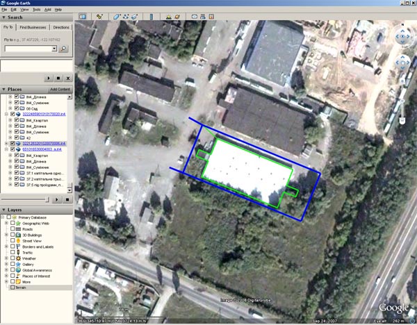
Reading/writing 3D models in the Google Earth KMZ format

Reading/writing of KMZ files was improved. Now 3D models are also supported.

KMZ is the native format of Google Earth. KMZ is a conventional ZIP archive that may contain any files (try to rename *.KMZ into *.ZIP and you will be able to browse its contents with any archiver). To open KMZ file in Google Earth it must contain a KML file.

KML is a format based on XML vector objects. It can describe polygons, polylines, points. 3D models are stored separately from KML in DAE files.

DAE files store objects in 3D graphics COLLADA format. COLLADA format is also based on XML and is the most advanced format for 3D graphics exchange. Textures of 3D models in JPEG, PNG and TIF formats are saved directly in KMZ. It is also possible to open COLLADA format files independently from KMZ. In such case all textures must be in the same folder with DAE file.

A large collection of 3D models in KMZ format is available on Google 3d Warehouse. Here are some examples:

Triumphal arch (Paris)
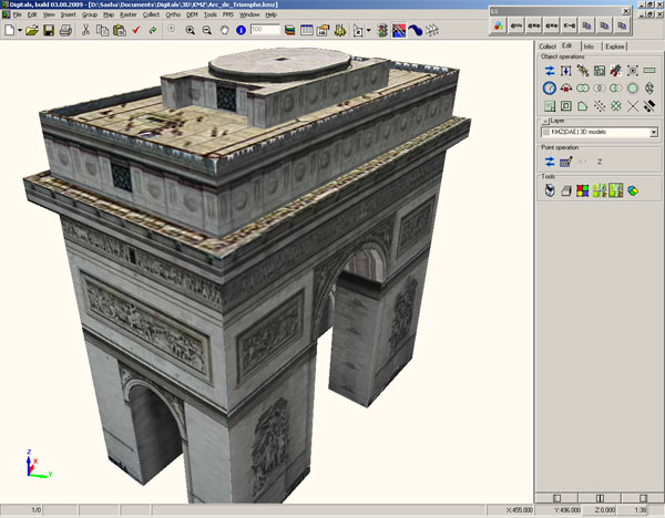
Image

Video system

Image

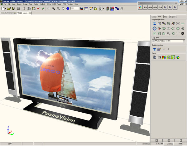
The last example demonstrates the possibility to load any models and not only buildings.

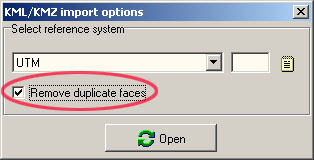
If some surfaces of a model are displayed without textures you have to turn on View>Hide internal surfaces in the context menu (right mouse button) of View>3-Dimensional. Another way is to check Remove duplicate faces option in KMZ import dialog.

Image

Examples: 
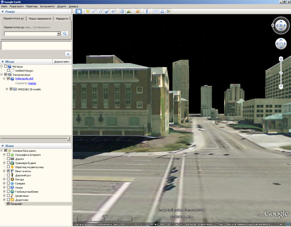
Indianapolis (state of Indiana, USA) in DMF format, Indianapolis exported from Delta/Digitals in KMZ format.

Image

Due to support of COLLADA(*.DAE) format you can export 3D models in popular 3D modelers like Autodesk 3ds Max or Autodesk Softimage.

_________________
Delta/Digitals developers team


Top
 Profile  
 
 Post subject: Re: New software features
PostPosted: 19 Apr 2011, 07:42 
Administrator
Administrator
User avatar

Joined:
10 May 2005, 14:01
Posts: 26
New update of BlockMSG version 5 is released

BlockMSG is rigorous bunlde adjustment program that supports big and complex blocks and uses GPS projection centers with automatic antenna offset calculation.

Download BlockMSG5 installation >>>

_________________
Delta/Digitals developers team


Top
 Profile E-mail  
 
 Post subject: Re: New software features
PostPosted: 22 Aug 2011, 17:47 
Administrator
Administrator
User avatar

Joined:
10 May 2005, 14:01
Posts: 26
Selection of orthophoto interpolation quality (Tools|Options|Edit|Orthophoto)

New orthophoto interpolation modes can improve the quality of images after orthophoto rectification. Standard interpolation is the fastest, but does not remove noise, pixelate lines and moire that appear due to resampling of original raster (photo) to a new resolution (ortho). Super interpolation mode provides the best image quality of rectified images, but doubles the rectification time.

The quality difference is only visible on multiple zoom magnification.

Comparison of interpolation modes (zoom 4:1)
Image

_________________
Delta/Digitals developers team


Top
 Profile E-mail  
 
 Post subject: Re: New software features
PostPosted: 09 Nov 2011, 14:19 
Administrator
Administrator
User avatar

Joined:
10 May 2005, 14:01
Posts: 26
Creating PRJ-files on saving to ArcGIS Shape format (*.shp)

ArcGIS keyword in datums description file (Datums.ini) allows to define projection/datum description in ArcGIS format.

For example:

ArcGIS=PROJCS["Pulkovo_1942_GK_Zone_5",GEOGCS["GCS_Pulkovo_1942",DATUM["D_Pulkovo_1942",SPHEROID["Krasovsky_1940",6378245.0,298.3]],PRIMEM["Greenwich",0.0],UNIT["Degree",0.0174532925199433]],PROJECTION["Gauss_Kruger"],PARAMETER["False_Easting",5500000.0],PARAMETER["False_Northing",0.0],PARAMETER["Central_Meridian",27.0],PARAMETER["Scale_Factor",1.0],PARAMETER["Latitude_Of_Origin",0.0],UNIT["Meter",1.0]]

If datum assigned to a map (Map|Properties) has such description and map is saved to ArcGIS Shape then *.prj file will be created along with *.shp, *.shx and *.dbf files.

View Datums.ini sample >>>

Using MapInfo keyword it is possible to add datum description in MapInfo format.

For example:

MapInfo=CoordSys Earth Projection 8, 1001, "m", 21, 0, 1, 4500000, 0 Bounds (-3749281.53901, -10002137.4978) (12749281.539, 10002137.4978)

When save map to MapInfo MID/MIF this description will be written to CoordSys clause in MIF-files header.

_________________
Delta/Digitals developers team


Top
 Profile E-mail  
 
 Post subject: Re: New software features
PostPosted: 08 Feb 2017, 09:09 
Administrator
Administrator
User avatar

Joined:
10 May 2005, 14:01
Posts: 26
Support for multispectral raster images

For images that are more than three color channels, you can choose which of them will be displayed on the screen (DIPEdit|View|Select channels...). Selection is stored in RGB.map file in the raster folder and subsequently used when you open any image in that folder.

RGB.map file contains lines of the form R:4 G:2 B:3, which specify the number of channels (bands) of the original image displayed in the color in RGB-space monitor. If RGB.map has more than one line, the color presets can be switched in Ged by key combinations Shift+PgDn and Shift+PgUp.

For example, for a four-band raster containing an additional infrared channel, RGB.map might look like this:

R:1 G:2 B:3
R:4 G:2 B:3


In the second case, the fourth infrared channel is put in place of red (falsecolor image).

_________________
Delta/Digitals developers team


Top
 Profile E-mail  
 
Display posts from previous:  Sort by  
Post new topic Reply to topic  [ 15 posts ] 

All times are UTC


Who is online

Users browsing this forum: No registered users and 1 guest


You cannot post new topics in this forum
You cannot reply to topics in this forum
You cannot edit your posts in this forum
You cannot delete your posts in this forum
You cannot post attachments in this forum

Search for:
Jump to:  
cron
Powered by phpBB © 2000, 2002, 2005, 2007 phpBB Group